Principle and scheme design of photovoltaic flexible Mounting
 Publish Time:2021-12-21
 Sources:garcesolar
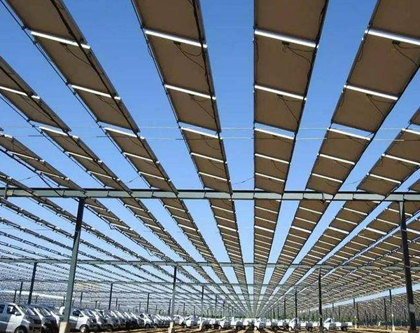
The flexible Mounting adopts the method of tensioning the prestressed steel strand between two points. These two fixed points use steel foundation to provide reaction force, and a large distance of 10-30 m can be realized. This design can avoid the unfavorable factors of mountain undulations and high vegetation, and only set base points and tension pre-stressed steel strands at appropriate locations; at the same time, in deep-water fishing ponds, it can also be achieved while maintaining the same water level. Construction of foundation and flexible Mounting.
The steel strand is used as a fixed Mounting for component installation. The calculation should consider the working conditions under different load combinations of dead weight, wind pressure and snow pressure, and conduct stress analysis. Different from the rigid deformation requirements of traditional supports (main beam L/250, secondary beam L/200 [1]), flexible Mounting have no strict restrictions on deformation. At present, the allowable deflection value L/30~L/15 can be adopted according to the actual situation. Under this deformation condition, the mechanical properties of the steel strand will not be affected.
Therefore, the flexible Mounting can better adapt to the large-span scheme, and at the same time, the total cost can be controlled. The flexible Mounting scheme is to change the purlins of the traditional rigid Mounting scheme to steel strands. Its characteristic is that the steel strand adopts the one-wire method to provide pretension. After the components are installed, the steel strand is allowed to have certain deformation under different working conditions (this article discusses according to the allowable deflection value L/30), so as to realize a large span Mounting of 10~30m to meet the needs of different terrains.
Due to the existence of the prestressing force of the steel strands, the column top will generate a large horizontal tension force, resulting in a large bending moment at the bottom of the foundation. Therefore, generally the column top diagonal pull or support scheme is used to balance the horizontal force generated by the pretension to meet the force requirements of the column bottom against overturning.
According to the overall design scheme and the force characteristics of the flexible Mounting, the foundation can take two forms: Foundation scheme 1: Two foundations are used, one is a steel column foundation, which mainly provides the response to the vertical force of the flexible Mounting; in addition, it should be set The stay cable foundation can bear the horizontal force generated by the steel strand, and bear the upward tension and the correct tension. The stay cable foundation belongs to the counterweight type foundation scheme 2: Two foundations are used, one is a steel column foundation, which mainly provides the reaction force of the flexible Mounting vertical force; in addition, a diagonal brace Mounting foundation should be set up to withstand the tension generated by the steel strand , The steel strand should generate downward pressure and right thrust to the diagonal bracing foundation. The bottom area of the diagonal Mounting column foundation is slightly smaller than the bottom area of the foundation scheme 1. According to the layout of the photovoltaic modules, the flexible Mounting scheme can be divided into horizontal and vertical; according to the span length, single-span and multi-span schemes can be used. However, due to site conditions, single-spans often cannot meet the needs, so two-spans, three-spans, or even larger spans need to be used.
The photovoltaic module flexible Mounting system is a new type of Mounting system that simplifies the module Mounting system by fixing the photovoltaic module on a steel strand tensioned between two columns. This is a new structure, and there is not enough design basis in industry codes and standards; the system uses the axial tension of the tensile steel strands to resist lateral loads, such as member gravity, snow load and wind load.
At the same time, changes in ambient temperature will cause expansion or contraction of the steel strands, leading to changes in prestress and an increase or decrease in the displacement of the steel strands. Therefore, on the one hand, it should be ensured that when the temperature rise reaches the design maximum, the displacement of the steel strand still meets the stiffness condition;